Where is the remote? Wouldn't it be good if you could switch channels on the television from a website. A wanted to see if it is possible. It didn't.. Note to self; buy more powerful IR transmitters.


Where is the remote? Wouldn't it be good if you could switch channels on the television from a website. A wanted to see if it is possible. It didn't.. Note to self; buy more powerful IR transmitters.
I am trying out Hardware-in-the loop simulation on a new Arduino project for a client. Test driven development is unfortunately not very big in the Arduino community (yet) so I decided to implement something by myself. The setup is simple:
A test case could for example be, when the user presses a button a LED should light up. The second Arduino will output a signal to the button input on the first Arduino, and then check if the LED pin output is high. Example code is shown below.
void loop() {
  // Simulate that user presses button
  digitalWrite(BUTTON_PIN, 1);

  // check that the LED lights up
 assert(LED_PIN, 1);

 delay(500)

  // check that some actuator starts running
  assert(ACTUATOR_PIN, 1);

  // Simulate that user releases button
 digitalWrite(BUTTON_PIN, 0);

  // Led and actuator should turn off
 assert(LED_PIN, 1);
 assert(ACTUATOR_PIN, 1);

  // stop execution
 while (1) {}
}

bool assert(uint8_t pin, bool expectedState) {
 bool state = digitalRead(pin);
  if (state != expectedState) {
   Serial.print("## FAILURE: pin ");
   Serial.print(pin);
    Serial.print(" == ");
   Serial.print(state);
    Serial.print(" != ");
   Serial.print(expectedState);
    Serial.println();
   return false;
 }
 else {
    Serial.print("## OK: pin ");
    Serial.print(pin);
    Serial.print(" == ");
   Serial.print(state);
    Serial.println();
   return true;
  }

}
It might seem unnecessary, (and it is for simple problems), but it does increase code quality and decreases the risk of bugs being introduced when writing new features to the code.
I would like to write my test code in Python on a laptop and control an Arduino (via Firmata for example). Then I would have proper tools for testing and generating test reports. For now the Arduino solution is sufficient though.
Att bo i Göteborg innebär att man många morgnar ställer sig själv frågan "behövs ett paraply idag?". För att överlämna fler små beslut till datorer programmerade jag en mikroprocessor som svarar med att tända en lysdiod om paraply rekommenderas.

Idéen är väldigt enkel. Mikroprocessorn läser väderprognosen från yr.no för de kommande 10 timmarna (vilket är ungefär den tiden jag väntas vara hemifrån). Om någon av dessa timmar innehåller regn (högre än några få mm) så tänder den lysdioden. Släckt lysdiod innebär givetvis inget regn.
Jag kör ett php-skript som hämtar kommande prognos från yr.no. Den är publicerad på https://sebastiannilsson.com/will-it-rain/ och är relativt enkel att använda.
Exempel: Prognosen för Göteborg med ett gränsvärde för regn vid 0.5 mm ser ut såhär:
https://sebastiannilsson.com/will-it-rain/index.php?debug=1&threshold=0.5&yr_url=http://www.yr.no/sted/Sverige/V%C3%A4stra_G%C3%B6taland/G%C3%B6teborg/
Kod för skriptet som visar hur man använder yr.no som ett väder-API.
Spark Core är en mikroprocessor som ansluter till Wifi. Man laddar över kod till den över deras molntjänst.

Jag håller på att bygga om min självbalanserande robot och behövde då ett smidigt sätt att styra motordrivaren L298n. Eftersom jag styr roboten med PID-regulatorer ville jag att mitt bibliotek ska ta flyttal som både är negativa och positiva. Resultatet blev ett motordrivar-bibliotek som är väldigt enkelt att använda:
/* This example shows how to set motor speed in percentage where a negative
   value will run the motor backwards.
   This is very usuful in control applications. For example the output
   from a PID controller is most often a float and can be integrated with
   this library easily.
*/
#include <L29x.h>
L29x motorLeft(9, 22, 23); // enable (PWM), motor pin 1, motor pin 2
L29x motorRight(8, 24, 29); // enable (PWM), motor pin 1, motor pin 2

void setup() {
  // put your setup code here, to run once:

}

void loop() {
  motorLeft.setSpeedPercentage(-12.34);
  motorRight.setSpeedPercentage(-10);
  delay(3000);
  motorLeft.setSpeedPercentage(100);
  motorRight.setSpeedPercentage(90);
  delay(3000);
}
IMU står för inertial measurement unit och innebär kort en enhet som känner av riktning, hastighet och gravitationskrafter. De sitter exempelvis i telefoner för att rotera skärmen beroende på i vilken vilken man håller den. De går att köpa från Sparkfun eller om man är sparsam från ebay. De består oftast av chip-kombinationen ITG3205 (gyro), ADXL345 (accellerometer) och HMC5883L (kompass). Att använda varje chip var för sig ger inte speciellt mycket men kombinationen ger desto mer. En video visar detta bättre (dock med en annan IMU):
http://www.youtube.com/watch?v=x1vpl6H42Mo
Det finns tyvärr relativt dålig dokumentation till hur man får igång en IMU i Arduino varför jag här publicerar ett enkelt exempel.
Jag har nu fått tillräckligt många delar för att börja montera roboten.


Jag blev tvungen att borra upp hålen något för att få dem att passa M3.


Accellerometern sätts så nära motoraxeln som möjligt.


Smart grej för att dra åt alla muttrar är att ta en skruvdragare, en bit tejp och därefter snurra den gängade stången. Håll fast muttern med fingrarna och låt borrmaskinen göra jobbet. Annars tar det ett bra tag att få dit alla 24 muttrar.


Såhär ser den ut just nu:


Jag ville testa att löda ytmonterat och köpte mig därför adapter från TQFP32 till vanlig dip att sätta i breadboard.
Skaffa adapter från TQFP32 till dip. Chip att löda fast är i det här fallet en Atmega328P-AUR.
")
")
Tänk på att det är lättare att löda med flux:
")
Såhär ser det ut när man alla ben och headers sitter på plats:
")
Montera på breadboard och bränn in Arduino Uno bootloader:
")
Klart. Atmega328P-AUR på en breadboard med Arduino Uno bootloader:
")
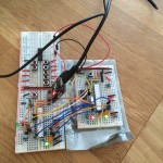
Förbättrade nyligen hårdvaran för att fjärrstyra min dammsugare över internet. Tidigare använde jag ett helt Arduino Uno-kort vilket är overkill. Bättre och snyggare blir det att göra det direkt på en breadboard. Video när det fungerar (med lite annan hårdvara).
1. Koppla upp Atmega328 på breadboard för att få en Arduino Uno.
2. Dra kablar från varje knapp på fjärrkontrollen.
3. Sätt dit ett gäng transistorer. En för varje knapp du vill fjärrstyra. Kom ihåg att kombinera jord för breadboard och fjärrkontrollen. Jag satte också dit några lysdioder för att lättare se vilket kommando som skickas.


4. Tejpa kablarna så att de sitter på plats.

5. Tejpa fast breadboard på fjärrkontrollen. Detta gör den mer intakt och risken för att kablar lossnar minskar.

6. Koppla in till datorn och konfigurera eventghost till att styra roomba.
Nu ikväll gjorde jag cad och beställde delar till att göra en egen självbalanserande robot. Kommer att använda Arduino som mikroprocessor och en liten 6 degrees of freedom som tilt-sensor.
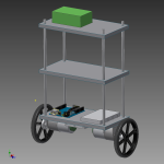


Cadden på bilderna är inte helt klar men jag tror att de flesta delar är på sin rätta plats.
Uppdatterar med nya blogginlägg allt eftersom framsteg blir gjorda.
La till skruvförband till motorfäste, hjul och de stängerna. Uppdaterade bilder:


Att sätta ihop sin egen Arduino på en labbplatta är ingen större konst. Visar här några illustrationer som förklarar hur man gör. Du kan köpa ett arduino-kit från mät.se för att få allt du behöver.
Enklaste konfigurationen som kräver en ftdi-kabel:

Vill man kunna mata denna koppling med ström från ett batteri lägger man bara till en några få komponenter. Finns att köpa här.

Istället för en ftdi-kabel kan man sätta dit en usb-modul såhär. Länk till usb-modul.

