EnglishSvenska

Our game Bananpiren has launched!


After years of inactive development I have decided to release the game I made together with my brother; Bananpiren. It is a game where you control a banana boat in Gothenburg. Your task is to transport as many banana crates as possible. Give it a try!

The game was my first game project in Unity3D. Great fun creating a game, but even a very simple game like this took more time than I would like to admit to finish. Let's see if I ever make a second one. Maybe if this one becomes a great success.

Västtrafik Monitor v2

Västtrafik har uppdaterat sina api:er vilket gjorde att min bussmonitor slutat fungera. De hade gjort det lite klurigare med Oauth2 men i övrigt var det mest att byta url till https://api.vasttrafik.se/bin/rest.exe/v2/departureBoard

All kod finns på Github.

Infrared experiments to control the television from a website

Where is the remote? Wouldn't it be good if you could switch channels on the television from a website. A wanted to see if it is possible. It didn't.. Note to self; buy more powerful IR transmitters.

HIL testing in Arduino

I am trying out Hardware-in-the loop simulation on a new Arduino project for a client. Test driven development is unfortunately not very big in the Arduino community (yet) so I decided to implement something by myself. The setup is simple:

  1. One Arduino is running the application software.
  2. Another Arduino connects to inputs and outputs on the first Arduino. This Arduino will include all the test code.

2015-05-14 16.08.09

A test case could for example be, when the user presses a button a LED should light up. The second Arduino will output a signal to the button input on the first Arduino, and then check if the LED pin output is high. Example code is shown below.

void loop() {
  // Simulate that user presses button
  digitalWrite(BUTTON_PIN, 1);

  // check that the LED lights up
 assert(LED_PIN, 1);

 delay(500)

  // check that some actuator starts running
  assert(ACTUATOR_PIN, 1);

  // Simulate that user releases button
 digitalWrite(BUTTON_PIN, 0);

  // Led and actuator should turn off
 assert(LED_PIN, 1);
 assert(ACTUATOR_PIN, 1);

  // stop execution
 while (1) {}
}

bool assert(uint8_t pin, bool expectedState) {
 bool state = digitalRead(pin);
  if (state != expectedState) {
   Serial.print("## FAILURE: pin ");
   Serial.print(pin);
    Serial.print(" == ");
   Serial.print(state);
    Serial.print(" != ");
   Serial.print(expectedState);
    Serial.println();
   return false;
 }
 else {
    Serial.print("## OK: pin ");
    Serial.print(pin);
    Serial.print(" == ");
   Serial.print(state);
    Serial.println();
   return true;
  }

}

Why the hassle?

It might seem unnecessary, (and it is for simple problems), but it does increase code quality and decreases the risk of bugs being introduced when writing new features to the code.

Making it better

I would like to write my test code in Python on a laptop and control an Arduino (via Firmata for example). Then I would have proper tools for testing and generating test reports. For now the Arduino solution is sufficient though.

Taggad med:

Formula Student Baltic Open 2014

Sensommaren och hösten kunde ha blivit utan praktiskt ingenjörsjobb om det inte vore för att jag blev övertalad att bygga räserbil. Målet var Baltic Open i Estland och dit skulle vi ta CFS13 och CFS13e (alltså både den bensin- och eldrivna bilen).

Taggad med: ,

Självbalanserande ARM (uppdaterad och bättre)

Simplicity is the ultimate sophistication. I den förra versionen av den självbalanserande roboten använde jag totalt 3 mikroprocessorer men har nu designat och programmerat om den på en större ARM mikroprocessor. Med mer kräm i processorn ges en mängd fördelar:

  • Färre komponenter
  • Enklare kretsschema
  • Robust mekanisk design på grund av färre kablar
  • Ingen kommunikation mellan processorer är nödvändig vilket ger en mycket enklare kod
  • Ett litet RTOS sköter trådhanteringen (vilket inte gick på AVR)


Så bygger man en likadan (eller bättre)

Komponenter

Mekanisk design

Läs de äldsta inläggen på projektsidan för att se foton från hur man bygger ihop den. Det enda som behöver tillverkas är de tre plattorna för vilka det finns CAD och ritningar.

Kretsschema

Många har frågat om kretsschema så jag gjorde ett i Altium Designer.

Mjukvara

All kod ligger på Github.

Reglerteknik

Kort använder jag kaskadåterkopplade PID-regulatorer. Den yttre loopen reglerar hastigheten på roboten vilket mäts på tachometrar på motorerna. Den intre loopen reglerar robotens vinkel vilket mäts med en IMU. Den yttre loopen har långsam dynamik och den intre loopen är mycket snabbare. Rent teoretiskt ska det gå att göra en självbalanserande robot med endast den inre loopen men man får väldigt lätt ett beteende av att roboten långsamt rör sig framåt eller bakåt över golvet eftersom återkopplingen från hjulens hastighet saknas.

För att få ytterliggare bättre prestanda används gain scheduling på den inre loopen vilket innebär att regulatorparamterarna ändras beroende på robotens vinkel. En liten vinkel nära jämviksläget innebär konservativa regulatorparametrar där endast små justeringar görs för att hålla roboten stående. Är vinkeln stor är roboten nära att ramla och de aggressiva paramterinställningarna aktiveras med syfte att göra allt för att återfå stabilitet.

Information flow

Information flow

Cascade PID implementation theory

Cascade PID implementation theory

Ändra parametrar

Troligtvis kommer alla parametrar inte fungera utan att de justeras något. I koden finns en struct som kan sättas i setConfiguration(). Smartare är dock är att använda en seriell terminal för att ändra parametrar samtidigt som koden körs. På så sätt behöver man inte programmera om processorn varje gång man vill ändra en parameter. Öppna Serial Monitor i Arduino. Testa att skriva "print configuration" till Arduinon. Om allt fungerar som det ska kommer den svara med att skriva ut alla parametrar. Alla variabler i structen Configuration kan sättas från terminalen. Skriv bara "set" följt av variabelnamn och värde. Exempelvis "set speedPIDKp 1.5". För att aktivera debug skriver du "set debugLevel 2". Om du vill debugga IMU skriver du därefter "set angleRawDebug 1". För att stänga av en debug-variabel skiver du exempelvis "set angleRawDebug 0".

Att hitta rätt regulatorparametrar

Använd en realtidsplotter när du ställer in dina regulatorparametrar så går det enklare.

Taggad med: , , , ,

Ska jag ta med paraplyet?

Att bo i Göteborg innebär att man många morgnar ställer sig själv frågan "behövs ett paraply idag?". För att överlämna fler små beslut till datorer programmerade jag en mikroprocessor som svarar med att tända en lysdiod om paraply rekommenderas.

Spark Core as Umbrella reminder

Idéen är väldigt enkel. Mikroprocessorn läser väderprognosen från yr.no för de kommande 10 timmarna (vilket är ungefär den tiden jag väntas vara hemifrån). Om någon av dessa timmar innehåller regn (högre än några få mm) så tänder den lysdioden. Släckt lysdiod innebär givetvis inget regn.

Hur det fungerar

Hårdvara

  • Spark Core
  • Breadboard
  • Lysdiod
  • Resistor
  • Usb-kabel för strömförsörjning

Väderprognos med php och yr.no

Jag kör ett php-skript som hämtar kommande prognos från yr.no. Den är publicerad på https://sebastiannilsson.com/will-it-rain/ och är relativt enkel att använda.

  1. Leta reda på den stad som du vill ha prognos för och kopiera urlen. Exempelvis för Göteborg är den http://www.yr.no/sted/Sverige/V%C3%A4stra_G%C3%B6taland/G%C3%B6teborg/ eller för Kolbäck http://www.yr.no/sted/Sverige/V%C3%A4stmanland/Kolb%C3%A4ck/
  2. Gå till https://sebastiannilsson.com/will-it-rain/index.php?debug=1&threshold=0.2&yr_url=<URL HÄR>

Exempel: Prognosen för Göteborg med ett gränsvärde för regn vid 0.5 mm ser ut såhär:
https://sebastiannilsson.com/will-it-rain/index.php?debug=1&threshold=0.5&yr_url=http://www.yr.no/sted/Sverige/V%C3%A4stra_G%C3%B6taland/G%C3%B6teborg/

Kod för skriptet som visar hur man använder yr.no som ett väder-API.

Kod på mikroprocessorn

Spark Core är en mikroprocessor som ansluter till Wifi. Man laddar över kod till den över deras molntjänst.

  1. Skaffa en Spark Core eller liknande och koppla upp den mot wifi.
  2. Kopiera in min kod för Spark Core. Det enda som behövs ändras är variabeln för url.
  3. Ladda upp
Taggad med:

Realtime data plotter

Debugging sensors on a microprocessor can be a hassle and the most used approach is to output the sensor values to a serial monitor. Realtime plotting is a better and more visual way of doing the same thing.

RealtimePlotterProcessing

  • Uppdaterar plot i realtid medan det fortfarande behandlas av mikroprocessorn
  • Plots live data from serial port. Microprocessor choice does not matter as long as it can send serial data to your computer.
  • 6 channels of data (and this can be increased if necessary)
  • Stapeldiagram i realtid
  • Linjediagram i realtid
  • You just send the data you want to debug with a space as delimiter like this "value1 value2 value3 value4 value5 value6". Floats or integers does not matter.
  • Open source
  • Robust. It will not crash because of corrupt data stream or similar.
  • Multi platform Java. Tested on OSX and Windows 8 (and should work on Linux as well).

I created this software to debug an Arduino Due on my self-balancing robot. To tune the controls of the robot I needed fast feedback to know if I was making progress or not. The video below demonstrates typical use of the realtime plotter:


Download

Download
You can also följa projektet på Github. If you make improvements to the source code, please share it by making a pull request at Github.

Installera och använda

Since I have an Arduino I will use it as example but any micro processor can be used.

  1. Ladda ner ProcessingIDE to run the code. It is a neat and useful IDE for doing graphical stuff.
  2. Download controlP5 gui library och packa upp den till mappen för Processing libraries
  3. Connect the Arduino to the usb or serial port of your computer.
  4. Upload the example code (RealtimePlotterArduinoCode) to the Arduino
  5. Check serial monitor (at 115200) and check that it outputs data in the format "value1 value2 value3 value4 value5 value6".
  6. Close the serial monitor (since only one resource can use the serial port at the same time).
  7. Open the Processing sketch and edit the serial port name to correspond to the actual port ("COM3", "COM5", "/dev/tty.usbmodem1411" or whatever you have)
  8. Kör koden

Advanced use

The realtime plotter can be expanded to also send commands to the microprocessor. The usual approach when programming microprocessors is to set some parameters in the beginning of the code, upload them to the processor, see the result, change the parameters again, upload, and so on until satisfactory performance is achieved. This iterative process takes a lot of time and a better approach is to send updated parameters to the microprocessor from your computer via serial data. For example I needed to tune some parameters on my robot and created a command panel that runs in parallell with the realtime plotter. For each change in parameters I immediately am able to see the result on the plotting screen. Example code of this is located in /RealtimePlotterWithControlPanel.

RealtimePlotterProcessingWithControlPanel

Mina kommentarer

I decided to send and receive the data as ascii characters instead of binaries. The greatest disadvantage is performance and ease of use is the main advantage.

In some sense the realtime data plotter can also be used as a very slow and limited digital oscilloscope. I would not recommend using it for any high frequency applications though.

Some comments about earlier approaches and the used libraries

I have tried many different ways of doing this. My first approach was Matlab but I had problems with it locking the serial port. It was a hassle to get it working and getting everything configured takes to much time. My second approach was Python and graphing libraries but this was still not very satisfactory. The Processing language together with a graph library and ControlP5 made the whole thing much easier.


Arduino-bibliotek för motordrivare L29x

l298n arduino library
Jag håller på att bygga om min självbalanserande robot och behövde då ett smidigt sätt att styra motordrivaren L298n. Eftersom jag styr roboten med PID-regulatorer ville jag att mitt bibliotek ska ta flyttal som både är negativa och positiva. Resultatet blev ett motordrivar-bibliotek som är väldigt enkelt att använda:

/* This example shows how to set motor speed in percentage where a negative
   value will run the motor backwards.
   This is very usuful in control applications. For example the output
   from a PID controller is most often a float and can be integrated with
   this library easily. 
*/
#include <L29x.h>
L29x motorLeft(9, 22, 23); // enable (PWM), motor pin 1, motor pin 2
L29x motorRight(8, 24, 29); // enable (PWM), motor pin 1, motor pin 2

void setup() {
  // put your setup code here, to run once:

}

void loop() {
  motorLeft.setSpeedPercentage(-12.34);
  motorRight.setSpeedPercentage(-10);      
  delay(3000);
  motorLeft.setSpeedPercentage(100);
  motorRight.setSpeedPercentage(90);      
  delay(3000);
}
Taggad med:

Generating an interface for robust manual control using Supervisory Control Theory


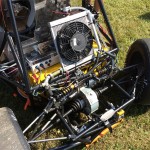
This is a project at Chalmers consisting of implementing a control system generated from Supervisory Control Theory.

Problem description

"Operation sequencing and resource safety is a non-trivial task within modern manufacturing systems. Typically, this task is handled manually which is time-consuming and error-prone. Whether a particular system works correctly is determined by how long it has been able to function without severe error. Obviously this situation is not sustainable and can be greatly improved by using software tools and mathematics to guarantee correct functionality. Such "model-based formal methods" is one main part of the research within the Automation group at Chalmers. This project aims at implementing a proof-of- concept of existing methods."

Present at IFAC 2014

Our paper was good enough to be presented by our examiner, Martin Fabian, at IFAC 2014. http://www.ifac2014.org/

Our solution

1. Create a model of the sequence:

Sequence to manufacture a full car

Sequence to manufacture a full car

2. Express it as automatas:

Representation of operations as automata

Representation of operations as automata

3. Extract guards to forbid bad behaviors e.g. deadlocks and forbidden states:

Guard extraction from non-blocking supervisor

Guard extraction from non-blocking supervisor

4. The HMI is implemented in HTML5 and AngularJS that communicates to the OPC server of the PLC:

The HMI with only executable operations being shown

The HMI with only executable operations being shown

overview

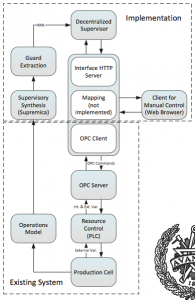
Overview of the system and the implementation


Download the article Robust Manual Control of a Manufacturing System using Supervisory Control Theory in collaboration with Martin Fabian.

Download the source code from Bitbucket

Taggad med: